Digital Design of Die Casting Dies for Zinc Alloy Castings - Die Casting Mold Design | Diecasting-mould
Digital design of die casting dies refers to the zinc alloy die casting mold design appears in a digital format. With the update of products in different industries such as automobiles and home appliances, the requirements of product quality, design and manufacturing levels are also getting higher and higher. This article introduces the design of the die casting mold of the watch case with convex parts, analyzing the design points of the pouring system, cooling system, and ejection system, and giving reasonable design parameters. This design method has a positive effect on shortening the design and manufacturing cycle of die casting molds, reducing production costs, and improving product quality. Taking zinc die casting watch case parts as an example, in addition to the high geometric accuracy requirements for the mold, the part has high requirements for the shape and position accuracy, and the delivery time is getting shorter and shorter. Using CimatronE software to design die casting molds, analyzing the design points of the pouring system, cooling system, and ejection system, offering reasonable design parameters, realize the digital design of mold design and greatly improve the efficiency of mold design.
Digital Design of Die Casting Dies for Zinc Alloy Castings
1. Design of main mold parts
This part has two pairs of symmetrically distributed convex parts. The conventional method is to use a lateral core pulling mechanism to smoothly demold, but the main body housing is symmetrically divided into upper and lower parts by the centerline of the convex parts. And the upper and lower parts are both tapered inward by 2º. The parting is completed by creating a curved parting surface at this position as the breaking surface, which can avoid using the core pulling mechanism. In addition, the wall thickness of this casting is not uniform. When designing the gating system, it is necessary to consider ensuring that all cavities can be filled effectively to obtain a better forming quality. According to the size of the part and actual production, a mold structure of one mold with two cavities is adopted. The 2330 standard mold base can be adopted in the design in order to ensure the core and cavity are fully closed. The gap parameters between the movable and fixed mold plates are set to 0.5mm each, and movable and fixed mold plates with sizes of 50mm and 70mm are selected as the standard mold plates. Set the height of the square iron to 80mm for the ejection system, and the default size of the software for the remaining templates.
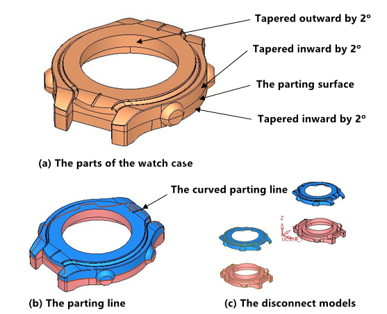
Design of parting surface parts
Using the surface curve design function of CimatronE software, make a curve based on the centerline of the convex part to break the surface of the watch case, and cut the model into two halves, one in the concave mold and another in the convex mold. Then use the parting function to quickly disconnect from the disconnected curved surface to form two curved surfaces, cavity and core parting, as shown in the above image. The next picture shows the process of creating a parting surface. Design a curved parting line based on the curve in the above image, and design this curved parting line into a parting surface to form a curved parting, avoiding the use of a lateral core pulling mechanism. The position of the watch chain has both beveled and curved surfaces, which can be done by complementing the curved surface step by step. Use the closed island function to create the center hole as an internal parting surface. Create a hybrid curved surface along the contour of the parting surface at the position of the watch chain, then create a combined curve with the outer contour of the curved surface. And create a sweeping surface with this curve. The other sweeping surface can be obtained by mirror images, see the following picture. Create a combined curve from the outer contour of the sweeping surface and other contours of the shell, and use this curve to create a sweeping surface. Mirror the created cavity shell parting surface to another cavity, and then use the ZX plane to cut the outer parting surface to complete the design of parting surface parts. These surfaces are grouped in the parting surface parts for the design of subsequent mold forming parts.
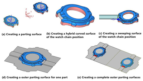
Design of core and cavity parts
Select the moving plate system to create a document named core. Use the sketching tool to create a sketch on the XY plane. Set the stretch positive increment to 45mm and reverse increment to 35mm, and the mold core design is completed by the parameterized removal function of the software. The cavity design can be completed in the same way as the fixed plate system.
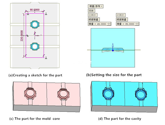
2. Design of the gating system
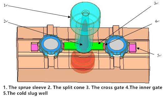
The size of the gating system varies with the die casting material, structure, and specific production conditions. There will be difficulties in discharging and residual scum defects due to the uneven thickness of the die casting. The two-sided pouring structure is adopted to obtain solidification in sequence and avoid shrinkage cavity. In order to prevent the molten alloy from flushing the bottom of the sprue, reduce the flow rate of the molten metal, and change the flow direction. The sprue adopts a flow cone and a split cone. The calculation of the gating system depends on the minimum cross-sectional area, and other cross-sectional areas can be determined according to the ratio.
Inner gate design
(1) Calculation of the cross-sectional area of the inner gate
In the formula, F is the cross-sectional area of the inner gate, cm³; T is the filling time, s.

(2) Calculation of filling time
The cross-sectional area of the sprue F is 0.37cm2 after calculation.

Gate sleeve and split cone design
The sprue used in the hot chamber die casting machine, which is mainly composed of a sprue sleeve and a split cone. The size of the sprue sleeve should be determined according to the structure of the casting during the design of the sprue sleeve. The diameter of the entrance of the sprue sleeve is set to be 8mm based on the die casting quality manual. In order to smoothly bring the molten zinc alloy to the cavity, increase the holding force of the molten alloy to the split cone, which is easier to keep the remaining material of sprue in the movable mold when the mold is opened. The unilateral demolding slope of the split cone is designed. The length L is from 50 to 70mm. The distance between the end face and the top of the split cone is l being 10 to 12mm, R being 4 to 5mm and h being 2.5 to 3.5mm. According to the right triangle theorem, the bottom diameter of the split cone can be obtained by the following formula:
In the formula, d3 is the diameter of the split cone at the bottom of the sprue, mm; L is the length, and is from 50 to 70mm. Take 60mm as the length, and d1 is the diameter of the entrance. d3 is 18mm calculated by the formula (4) and the large end diameter of the sprue sleeve is d2=d3+2h=18+2X2.5=23mm. The cross-section of cross gates with a single cavity is rectangular, and the size is 15mm×5mm. The cross-sectional area of single cavity F is 0.75cm2, and the cross-sectional area of two cavities F is 1.50cm2. The calculated cross-sectional area of the single cavity inner gate F is 0.31cm2, and the cross-sectional area of the two cavities F is within 0.62cm2. The actual cross-sectional ratio after optimization is calculated to be 1.61:1.50:0.62=2.60:2.42:1. The designed gating system is shown below.
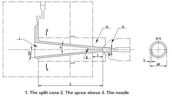
3. Design of cooling and ejection systems
Design of cooling systems
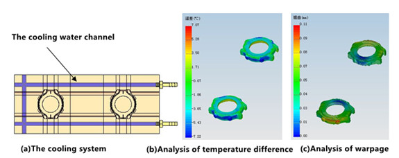
The working temperature of the alloy is from 150 to 200℃. In order to ensure the cooling effect, a water channel with a diameter of 6mm is used, and the distance between the hole wall and the cavity wall is 15mm. According to the structural characteristics of the die casting and the characteristics of the zinc alloy material, the cooling system is designed as shown below. Through analysis, the temperature difference is controlled at 3℃. The maximum warpage is 0.11mm, which is located at the left and right convex parts and can meet the needs of customers.
Design of ejector systems
This die casting is small, and the diameter of the ejector rod is 2mm. The single cavity is arranged evenly and symmetrically with 10 rods. In order to facilitate the demoulding and the removal of the remaining material, 4 push rods are added behind the split cone to ensure that the split cone can be pushed out and reset, and the gap is also conducive to discharge.
Applications of digital technology for die casting mold design and manufacturing can better optimize the product shape, mold structure, forming process, etc., significantly shorten mold design and manufacturing cycles, reduce production costs and improve product quality. The watch shell mold designed by this method can manufacture die casts with good quality after adjustment and a shorter development cycle of new products is obtained. This method can give some ideas for the development of similar products.

