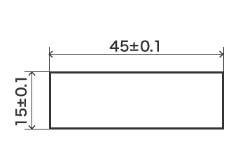
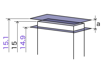
The precision of geometric parameters in mechanical parts is determined by both form tolerances and size tolerances. On the design drawings of mechanical parts, both size tolerances and geometric (form) tolerances are often specified simultaneously. Dimensional tolerances regulate the length, width, and other size aspects of each part, while geometric tolerances specify characteristics such as form, parallelism, inclination, position, and runout. The two have distinctions and connections. Depending on the usage conditions of mechanical parts, the precision requirements of geometric parameters determine the relationship between size tolerances and form tolerances.

In this article, we will deeply explore the differences and relationships between form (geometric) tolerances and size tolerances, and how to achieve conversions between them.
1. What is Form Tolerance?
1.1 – Form Tolerances Definition: Form Tolerance refers to the allowable deviation of a part’s shape or surface from its ideal geometric form. It ensures the part’s shape remains within specified limits, independent of its size, orientation, or position. In Geometric Dimensioning and Tolerancing (GD&T), form tolerance governs features such as straightness, flatness, roundness, and cylindricity.
1.2 – Form Tolerance Types & Symbols
Form tolerances are classified into four main categories:
- Straightness: Controls the straightness of a line element.
- Flatness: Controls the flatness of a surface.
- Circularity (Roundness): Controls the roundness of a circular feature.
- Cylindricity: Controls the roundness and straightness of a cylindrical feature.

1.3 – Form Tolerance Example
Why are geometric tolerances necessary? Consider the example of a designer ordering a plate-shaped part. If only dimensional tolerances are specified, the following issues may arise:
Without Form Tolerances:
A drawing with only dimensional tolerances may result in a part that, while meeting the dimensional requirements, is unsuitable due to issues like warping or misalignment.

With Form Tolerances:
Adding geometric tolerances such as “parallelism” and “flatness” ensures that the part will meet both dimensional and geometric requirements, avoiding the problems caused by dimensional tolerances alone.

1.4 – Form Tolerance Standards
The ISO standard for geometric tolerances primarily includes ISO 1101 and ISO 5458:
- ISO 1101: Specifies the basic concepts, definitions, and representation methods for geometric tolerances.
- ISO 5458: Outlines the measurement and evaluation principles of geometric tolerances.
2. What is Size Tolerance?
1.1 – Size Tolerances Definition: Size Tolerance, aka Dimension tolerance define the allowable variation in a part’s size. They are the absolute difference between the maximum and minimum permissible dimensions or the difference between the upper and lower deviations. This tolerance accounts for variations caused by factors like machining or measurement.
2.2 – Size Tolerance Symbols
Dimensional tolerances are typically represented using bilateral tolerances, such as 100 ± 0.1 mm, where the nominal size is 100 mm. Unilateral tolerances, such as 100 (+0.1/-0.3) mm, are used when a specific bias is needed.

2.3 – Size Tolerance Example
The choice of size tolerance affects the processing method. For example:
- ±1 mm: Rough machining (e.g., milling).
- ±0.1 mm: Rough machining followed by finishing.
- ±0.01 mm: Rough machining → finishing → grinding.
Narrower tolerances increase machining complexity and cost.
2.4 – Standard Size Tolerances
If no specific tolerance is stated, general tolerances are applied based on the nominal size. For example, according to a typical standard, a 50 mm dimension with medium precision would have a general tolerance of ±0.3 mm.
This chart applies to general tolerances for linear dimensions where no specific tolerance is mentioned:

3. Differences Between Form Tolerance and Size Tolerance
Now that you understand geometric and size tolerances, there are two main differences between the two:
3.1 – Adjustable Tolerance Range
The tolerance range for geometric and dimensional tolerances differs. Dimensional tolerances specify acceptable ranges for length or thickness but do not define the shape or alignment of a feature. Geometric tolerances, on the other hand, allow for detailed specifications of form, orientation, and position.
For example:
- Dimensional Tolerance: Specifies size but may permit irregular shapes.
- Geometric Tolerance: Specifies size, flatness, parallelism, and other geometric features.
3.2 – Measurement Methods
Dimensional tolerances are measured between two points, while geometric tolerances are measured against explicit standards. Dimensional tolerances only describe “length between two points,” leaving room for interpretation of shape or alignment. Geometric tolerances provide clear and consistent measurement standards for features like form, orientation, and position.
4. Relationship & Conversion Principles Between Size and Form Tolerances
The tolerance principle governs whether size tolerances and form tolerances can be interchanged. When the two tolerances are independent and cannot be converted, the independent principle applies. When they are interrelated and convertible, the related principle applies. The related principle is further divided into the envelope requirement, maximum material requirement, minimum material requirement, and reciprocal requirement.
4.1 – Basic Terms
- Local Actual Size (Dal, dal):
The measured distance between two corresponding points in any given cross-section of the actual feature. - Outside Envelope Size (Dfe, dfe):
Over a given length of the measured feature, the diameter or width of the ideal outer surface that is in contact with the actual inner surface, or the ideal inner surface that is in contact with the actual outer surface. For related features, the axis or center plane of the ideal surface must maintain the geometric relationship specified in the drawing with the datum. - Inside Envelope Size (Dfi, dfi):
Over a given length of the measured feature, the diameter or width of the ideal inner surface that is in contact with the actual inner surface, or the ideal outer surface that is in contact with the actual outer surface. - Maximum Material Effective Size (MMVS):
MMVS refers to the outside envelope size in the condition of maximum material. For inner surfaces, the MMVS is equal to the maximum material size minus the geometric tolerance (marked with the symbol ⊕). For outer surfaces, the MMVS is equal to the maximum material size plus the geometric tolerance value (marked with the symbol ⊕).
Formula:
MMVS = MMS ± t_geom- For outer surfaces, use the “+” sign.
- For inner surfaces, use the “–” sign.
- Minimum Material Effective Size (LMVS):
LMVS refers to the inside envelope size in the condition of minimum material. For inner surfaces, the LMVS is equal to the minimum material size plus the form tolerance (marked with the symbol ⊖). For outer surfaces, the LMVS is equal to the minimum material size minus the geometric tolerance value (marked with the symbol ⊖).
Formula:
LMVS = LMS ± t_geom- For inner surfaces, use the “+” sign.
- For outer surfaces, use the “–” sign.
4.2 – Independent Principle
The independent principle ensures that the geometric tolerances and dimensional tolerances specified in the drawings are independent of each other. Each must meet its respective requirements. When the independent principle is applied, the dimensional tolerance and geometric tolerance values are specified separately on the drawing without any additional markings.
For example, consider a part with a shaft diameter of Φ20 –0.018 mm and a straightness tolerance of Φ0.1 mm for the axis. Both tolerances should be treated independently, and each must satisfy its respective design requirements. The actual shaft diameter must be within the range of Φ19.982 mm to Φ20 mm, and the straightness error must be in the range of Φ0 to Φ0.1 mm. The maximum functional size of the shaft diameter can reach Φ20.1 mm, but under the independent principle, the functional size does not need to be controlled, and no integrated inspection for the diameter is required.
4.3 – Envelope Principle
If the symbol ⊕ is added after the size tolerance or tolerance zone code for a single feature on the drawing, it indicates that the feature is subject to the envelope requirement. The envelope requirement ensures that the actual feature complies with the maximum material boundary, i.e., the outside envelope size must not exceed the maximum material boundary, and the local actual size must not be smaller than the minimum material size.
For example, the feature must satisfy:
dfe ≤ Φ20 mm and dal ≥ Φ19.70 mm.
During inspection, the part is deemed qualified if the actual cylindrical surface can pass through a full-form gauge with a diameter equal to the maximum material boundary size of Φ20 mm, and the locally measured actual size is no less than Φ19.70 mm.
Thus, the envelope requirement controls both the actual size and geometric errors within the dimensional tolerance range.
4.4 – Maximum Material Requirement and Its Reciprocal Requirement
Suppose the symbol ⊕ is added after the geometric tolerance value or datum letter in the tolerance frame on the drawing. In that case, it indicates that the maximum material requirement is applied to the measured feature or datum. When the symbol ⊕ is followed by another symbol ⊙, it denotes the reciprocal requirement for the maximum material condition.
1) Maximum Material Requirement for Measured Features:
When applied to measured features, the geometric tolerance value is specified under the condition of maximum material. Suppose the actual profile deviates from the maximum material condition (i.e., the local actual size deviates from the maximum material size). In that case, the geometric error can exceed the geometric tolerance value given under the maximum material condition. The maximum allowable deviation is equal to the dimensional tolerance, while the local actual size must not exceed its maximum or minimum material sizes.
For instance, when the straightness tolerance of a shaft’s axis is subject to the maximum material requirement, the shaft must meet:
dfe ≤ Φ20.1 mm and Φ19.7 ≤ dal ≤ Φ20 mm.
During inspection, the part is deemed qualified if:
- The actual cylindrical profile passes a positional gauge designed with a maximum material boundary size of Φ20.1 mm, and
- The locally measured actual size is within the range of the maximum and minimum material sizes.
4.5 – Minimum Material Requirement and Its Reciprocal Requirement
If the symbol ⊖ appears after the geometric tolerance value or datum letter in the tolerance frame, it indicates the minimum material requirement. When the symbol ⊖ is followed by ⊙, it denotes the reciprocal requirement for the minimum material condition.
1) Minimum Material Requirement for Measured Features:
Under the minimum material requirement, the actual profile of the measured feature must not exceed the minimum material effective boundary. The local actual size must remain within the range of the maximum and minimum material sizes.
2) Reciprocal Requirement for Minimum Material Requirement:
When applied, the actual profile must not exceed the minimum material effective boundary. If the actual size deviates from the minimum material size, the geometric error can exceed the geometric tolerance value specified under the minimum material condition. Similarly, when the geometric error is smaller than the specified tolerance value, the actual size can exceed the minimum material size.
4.6 – Determining Geometric Tolerance Values
1) Specified Geometric Tolerance Values:
- General Rule: Geometric tolerances should follow the hierarchy: Shape tolerance < Position tolerance < Dimensional tolerance. Exceptions exist, such as the straightness tolerance of slender shafts, which may far exceed the dimensional tolerance.
- Orientation and Location Tolerances: Location tolerances should be larger than orientation tolerances. Generally, location tolerances can include orientation tolerance requirements, but not vice versa.
- Composite Tolerances: Composite tolerances should be larger than individual tolerances. For example, the cylindricity tolerance of a cylindrical surface can be greater than or equal to the roundness, straightness, or axis straightness tolerances.
2) Unspecified Geometric Tolerance Values:
For features where geometric tolerances are not explicitly noted on the drawing, general geometric accuracy requirements still apply.

