A properly designed runner system is needed for the normal working of mold. How to design the runner system correctly?
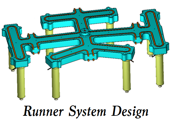
Importance of Runner System Design
Runner systems guide the melt from the vertical runner to the mold cavity, and additional pressure is required to push the melt through the runner system. When the melt flows through the flow channel system, the shear heat (friction heat) generated will increase the temperature of the melt and help the flow of the melt.
Although proper runner size has many advantages for a workpiece and mold design, the basic principle of runner size design is not widely understood, so the problem of runner size design is often ignored. It is generally believed that the large-size runner can use a lower pressure to promote the melt flow, but it requires longer cooling time, will produce more waste, and also requires higher clamping force. On the contrary, properly small-size flow channels can achieve the highest efficiency in the use of raw materials and energy consumption. The reduction limit of runner size is the injection pressure specification of the injection molding machine. The channel balance function of mold flow analysis can find out the optimized channel size, provide a good channel system, and fill the balanced channel and mold cavity with reasonable pressure drop.
A well-designed runner system has the following benefits:
1) You can determine the optimal number of mold holes
2) Confirm that the melt glue can fill the mold cavity
3) It can achieve balanced filling of multiple cavity system
4) It can achieve a balanced filling of the mold cavity with multiple gates
5) It can minimize waste
6) Make it easier to eject the workpiece
7) Achieve the optimization of energy use efficiency
8) Filling time/holding time/forming cycle time can be controlled
Runner System Design Rules & Tips
In the final stage of the runner design, the mold flow analysis software can help confirm the sensitivity of the flow rate to the runner system design and determine the appropriate forming conditions. For example, when the fishbone runner system is used, different pouring rates will lead to different filling modes. Generally speaking, a low pouring rate will first fill the mold cavity far away from the vertical runner; At a high pouring rate, the mold cavity close to the vertical runner is filled first.
The runner design has an absolute impact on the quality and productivity of plastic parts or castings. The runner design rules in this section provide the basic specifications for runner design.
(1) In terms of runner size, the runner section area should not be less than the vertical runner section area, so that the molten glue can flow to the gate area quickly. However, we must pay attention not to use too large caliber flow channels to reduce the waste quantity. The selection of cold runner diameter should take into account the ability to use standard tool processors. For most materials, a minimum diameter of 1.5 mm (0.06 inch) is recommended. The height and width of the trapezoidal channel are approximately equal, and each side has a slope of 5 °~15 °.
(2) Whenever the runner has branches, the diameter of the branch runner should be smaller than the diameter of the main runner, because only a small amount of molten glue will flow into the branch. Moreover, from an economic point of view, the amount of molten glue in the flow channel should be reduced to reduce waste.
(3) Considering the melt temperature, generally speaking, the small-size runner is better than the large-size runner, which can generate a large amount of viscous heat and effectively improve the melt temperature without using the high-temperature tube. Improper application of high-temperature feed pipe may lead to material cracking. However, a small-size runner system may solidify ahead of time, resulting in a short shot.
(4) A cold slug well must be designed at the junction of all flow channels to help melt glue flow into the flow channel system and mold cavity. At the intersection of the flow passage and another branch flow passage, a cold material well is usually set at the extension of the flow passage.
(5) The runner design must take into account the convenience of ejection and de-molding, and provide the appropriate profile and de-molding angle. For most materials, the runner surface must be polished to facilitate the melt flow and eject the workpiece. The extended runner system should use multiple sprue pullers and multiple ejection positions.
(6) When designing the hot runner system, the material supplier should be consulted to determine the correct manifold size and pouring amount.