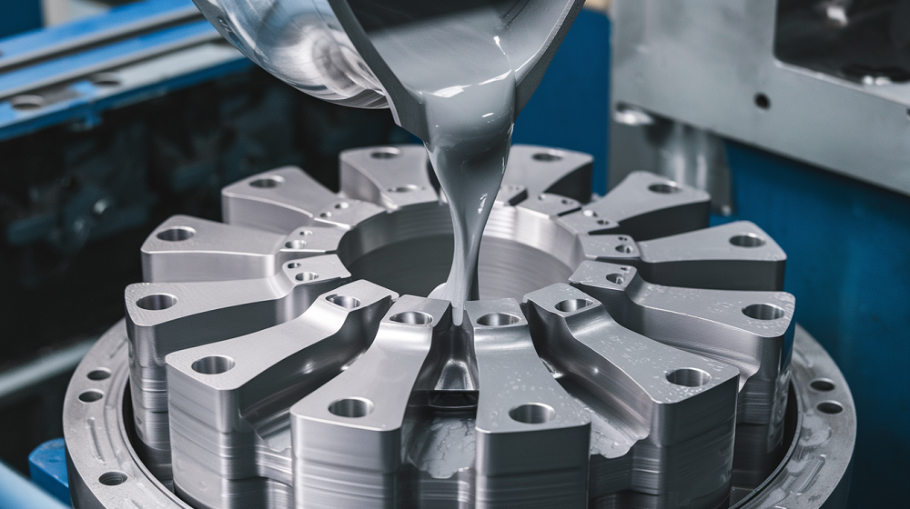
Here we are going to introduce the high-precision magnesium die casting process. It combines practical machining methods, process planning, tool selection, cutting parameters, and machining precautions to address the challenges of magnesium alloy components. The process ensures precision and reliability while overcoming the unique difficulties associated with magnesium alloys.

Magnesium Alloy Die Casting Process for High Precision Parts
Since the early 1990s, the application trends of major metal materials worldwide have changed. The use of traditional materials such as steel, copper, and zinc has slowed, while lightweight metal materials, represented by magnesium alloys, have risen significantly, with an annual growth rate of 20%.
Magnesium alloy, with a density of about 1.7×10³ kg/m³, is 1/3 lighter than aluminum alloy. It has excellent thermal conductivity, vibration damping, impact resistance, and wear resistance, along with the advantage of being 100% recyclable, aligning with contemporary environmental protection and sustainable development requirements. However, due to the unique properties of magnesium alloy – high chemical reactivity, a low melting point (650°C), and a high coefficient of thermal expansion (25.2×10⁻⁶/K) – its machining faces several challenges:

- High susceptibility to chemical corrosion.
- Combustibility during machining.
- Significant elastic deformation under cutting and clamping forces, making it difficult to achieve high machining precision.
Thus, it is necessary to explore and study the machining process for high-precision and complex magnesium alloy shell parts.
1. Material and Part Structure
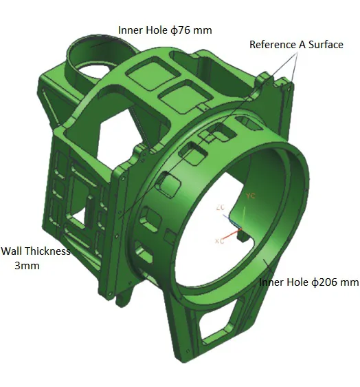
The part used to illustrate this process is an infrared bracket, a magnesium die-cast component made from ZM5 alloy. The infrared bracket has a complex structure and stringent machining requirements.
Key specifications include:
- Dimensions: 280 mm × 280 mm × 290 mm.
- Wall Thickness: As thin as 3 mm.
- Inner Hole φ206 mm: Cylindricity of 0.01 mm, surface roughness Ra = 0.4 μm.
- Inner Hole φ76 mm: Cylindricity of 0.006 mm.
- Assembly Surfaces (A): Flatness of 0.01 mm, surface roughness Ra = 0.4 μm.
These specifications highlight the precision required for magnesium die casting and machining.
2. Magnesium Die Casting Process Design
After analyzing the material and part structure, the following process plan was established for high precision magnesium die casting and subsequent machining.

Cooling Method
To avoid corrosion and ensure safety, cutting fluids are not used. Instead, air cooling is employed during machining to remove heat and chips effectively.
Machining Stages
The process includes three machining stages:
- Rough Machining: Removes the majority of excess material.
- Semi-Finish Machining: Shapes most features, such as grooves and external ribs.
- Finish Machining: Focuses on key surfaces and dimensions, leaving minimal cutting allowances to reduce stress and deformation.
Dimensional Stabilization
Between semi-finish and finish machining, a high-low temperature aging treatment stabilizes the dimensions of the part.
Clamping Technique
The “indicator alignment and pressing method” is used to prevent deformation during clamping. This ensures consistent dimensions before and after machining.
3. Specific Magnesium Die Casting Process
The specific implementation method of the process scheme is as follows:
1. Workspace Setup
The workspace for machining magnesium alloy parts must be ventilated, bright, and clean, with dry sand available nearby for fire suppression. Air cooling is used with a pressure of 0.45–0.50 MPa to remove chips promptly and carry away heat, preventing corrosion and combustion.
2. Cutting Allowance
During rough machining, most material is removed, and internal arcs and square grooves are shaped. Semi-finish machining shapes external ribs, bosses, and grooves, leaving 0.5 mm allowance for inner holes and surface A. Thin chips can raise local temperatures and cause combustion, so the minimum feed should not be less than 0.05 mm.
- Rough machining: 1.5 mm allowance.
- Semi-finish machining: 0.5 mm allowance.
- Finish machining: Done in three passes with remaining allowances of 0.30 mm, 0.12 mm, and 0.08 mm.
3. Aging Treatment
After semi-finish machining and before finish machining, a high-low temperature aging treatment is performed:
- The part is placed in a freezer at -50°C for 1 hour, then in an oven at 100°C for 1 hour.
- This cycle is repeated three times, with each transition completed within 1 minute.
- This process stabilizes dimensions, ensuring they remain unchanged during final machining.
4. Clamping and Positioning
Magnesium alloy’s high elasticity makes it prone to deformation under cutting and clamping forces, so measures are required:
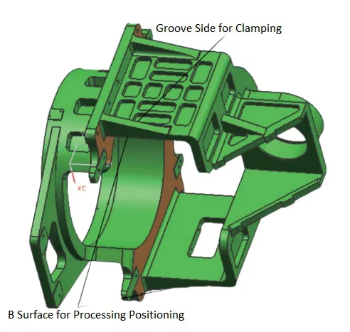
- Select a good reference surface for positioning.
- Apply clamping force on the positioning surface to avoid voids.
Use surface B as the reference plane, finish machining it to a flatness of 0.003 mm, and expose surface A while maintaining perpendicularity with surface B.
When machining the inner hole and surface A, place surface B on a support. Small clamps are used to press the workpiece inside the groove, and indicator alignment ensures surface A remains stable. This avoids deformation caused by clamping.
5. Tool Selection and Machining Parameters
For Machining surface A:
Rough Machining: A φ16 mm carbide end mill with a 4° rake angle, 11° relief angle, and 30° helix angle is used. Cutting speed: 5000 rpm, feed rate: 1500 mm/min.
Finish Machining: A φ16 mm carbide end mill with a 7° rake angle, 17° relief angle, and 35° helix angle is used. Cutting speed: 8000 rpm, feed rate: 1000 mm/min.
These tools and parameters reduce friction, heat, and deformation while improving machining quality.
For Machining Inner Hole φ206 mm:
Milling: A φ18 mm carbide end mill is used. Cutting speed: 8000 rpm, feed rate: 800 mm/min, leaving a 0.08 mm allowance for boring.
Boring: A φ206 mm boring tool is used. Cutting speed: 300 rpm, feed rate: 15 mm/min, with a tool tip radius r < 0.2 mm.
This combination ensures high precision without significant deformation.
The high precision magnesium die casting process we outline here address the challenges of machining magnesium alloy components. Through process planning, tool selection, cutting parameters, and effective machining techniques, the process ensures dimensional accuracy and geometric precision. The described approach reduces the risks of corrosion, flammability, and deformation associated with magnesium alloys, while meeting the requirements for complex and thin-walled components. This process provides a reliable method for manufacturing high precision magnesium die-cast parts.
Get High Precision Magnesium Alloy Die Casting Service from JunYing
At Diecasting-mould.com, we provide high-quality magnesium alloy die casting services designed to meet your exact specifications. Using advanced technology and skilled craftsmanship, we manufacture components with precision, durability, and consistent performance.
From complex geometries to thin-walled parts, we are equipped to handle a wide range of requirements, ensuring your products meet the highest industry standards. Our efficient processes and commitment to quality allow us to deliver reliable results for every project.
Visit Diecasting-mould.com today to request a quote and bring your ideas to production with precision and expertise!

