
The twist drill is the most commonly used hole-processing tool. The straight main cutting edge of this type of drill is long. The two main cutting edges are connected by a chisel edge. The chip groove is spiral (for easy chip removal). Part of the spiral groove constitutes the rake face. The rake face and the top angle (2Ø) determine the size of the rake angle g. Therefore, the drill tip rake angle is closely related to the helix angle and affected by the edge inclination angle.
Twist Drill Geometry
- 1. Vertex angle 2Φ
- 2. Rake angle
- 3. Back angle
- 4. Main deflection angle and face rake angle
- 5. Cross blade angle
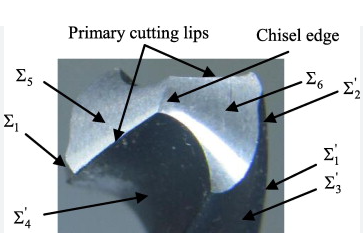
Vertex Angle 2Φ
It is the angle between the two main cutting edges projected in the midsection. The smaller the vertex angle, the longer the main cutting edge, the lighter the load on the unit cutting edge, and the reduced axial force, which is effective for the axial stability of the drill. The increased tip angle at the outer circle is conducive to heat dissipation and improved tool durability. However, a reduced vertex angle will weaken the drill tip strength, increase chip deformation, and increase torque. The standard twist drill vertex angle is about 118°. HSS high-speed steel drill: The vertex angle is generally 118 degrees, sometimes greater than 130 degrees, HM carbide drill: The vertex angle is generally 140 degrees; straight groove drills are often 130 degrees, and three-edge drills are generally 150 degrees.
Rake Angle
The angle between the rake face and the base surface in the orthogonal plane. The relationship between the rake angle of any selected point on the main cutting edge and the helix angle, main deflection angle, and rake angle of that point is tan=tan/sin+tancos (2-3). As the helix angle gradually decreases from the outer radius to the drill center, the rake angle also gradually decreases (negative values increase). When the main deflection angle is constant, the rake angle becomes smaller, from about +30° to -30°, and the cutting conditions near the center of the drill are very poor.
Back Angle
The back angle of any point on the cutting edge is the angle between the cutting plane and the back face of the point. The back angle of the drill is not measured in the main section but in the assumed working plane (feed section). In the drilling process, it is this back angle that works, and it is also convenient to measure. The back angle of the drill is obtained by grinding. When grinding, pay attention to grinding it smaller at the outer edge (about 8°~10°) and larger near the drill center (about 20°~30°). The reason for such sharpening is to adapt the back angle to the change of the front angle of the main cutting edge, so that the wedge angles of each point are roughly equal, to achieve a relative balance of sharpness, strength and durability, and to compensate for the effect of the reduction of the actual working back angle of each point on the blade due to the axial feed movement of the drill bit, and at the same time improve the working conditions of the chisel edge.
Main Deflection Angle and Face Rake Angle
The main deflection angle of the selected point on the main cutting edge of the twist drill is the angle between the projection of the main cutting edge on the base surface of the point and the drilling feed direction. Since the base surfaces of each point on the twist drill’s main cutting edge are different, each point’s main deflection angle also changes accordingly. After the twist drill is ground out to a vertex angle of 2Φ, the main deflection angles of each point are determined, and the relationship between them is tan=tanΦcos formula (2-2)—-The face rake angle of the selected point is the angle between the projection of the main cutting edge in the end surface and the base surface of the point. Since the absolute value of the inclination angle of each point on the cutting edge gradually increases from the outer edge to the drill center, the main deflection angle of each point on the cutting edge is also large at the outer edge and small at the drill center.
Cross Blade Angle
The cross blade is a section of the cutting edge on the end face of the twist drill that is perpendicular to the axis. The angles of the cutting edge include the cross-blade bevel angle, the cross-blade rake angle, and the cross-blade clearance angle.
- (1) The cross-blade bevel angle is the angle between the cross-blade and the main cutting edge in the end plane. It is naturally formed when the drill is sharpened. For a standard twist drill with a normal top angle and clearance angle, the larger the clearance angle, the smaller the angle. A reduction in angle will increase the length of the cross blade.
- (2) Since the base surface of the cross-blade is located inside the tool body, the cross-blade rake angle is a negative value.
- (3) Cross-blade clearance angle Cross-blade clearance angle. For a standard twist drill, =-(54°~60°), =30°~36°. Therefore, the metal extrusion and deformation at the cross blade is serious during drilling, and the axial force is very large.
Experiments show that when using a standard twist drill, about 50% of the axial force is generated by the chisel edge. For twist drills with larger diameters, the chisel edge generally needs to be ground to reduce the axial force.